|
计算机科学论坛
纹理映射在三维图形程序设计中具有非常重要的作用,三维场景中的许多特殊效果都是通过纹理映射来实现的。例如通过纹理映射模拟复杂的光照效果,物体表面对周围环境的反射效果等。
多层纹理映射
Direct3D最多支持8层纹理,也就是说,在一个三维物体的表面可以同时拥有1~8张不同的纹理贴图。Direct3D能够在一个渲染过程中把这些纹理颜色依次混合,渲染到同一个物体的表面。每一个纹理层对应0~7的索引序号,多层纹理映射能够模拟更为真实的三维世界。例如,要显示具有周围景物倒影的光滑大理石地板,可以把大理石地板贴图设置为纹理层0,把具有周围景物倒影的贴图设置为纹理层1,然后通过设置Direct3D多层纹理混合操作,把纹理层0和纹理层1相混合,这时绘制出的三维物体就同时具有大理石地板和景物倒影的纹理颜色。利用Direct3D多达8层的纹理混合,可以在图形显示系统中显示丰富多彩的图像。Direct3D多层纹理混合过程如下图所示:
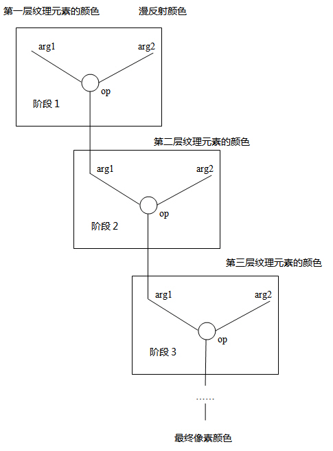
从上图可以看出8层纹理是逐层混合然后输出的,也就是说,最对需要8个阶段完成纹理映射,而且每一阶段都是独立进行的,针对每一阶段都需要设置相应的颜色和alpha混合方法。所以一个纹理层就相当于一个纹理阶段,多层纹理映射有时也称为多阶段纹理混合。其中,是否应用纹理层0~7,即是否进行0~7纹理阶段的操作,可由应用程序指定,但它们的选择必须是顺序的。也就是说,在没有使用第n层的情况下,第n+1层不能使用。
默认情况下,第一个纹理阶段操作(阶段0)的默认操作是D3DTOP_MODULATE,其他纹理操作阶段的默认操作是D3DTOP_DISABLE。即默认情况下Direct3D使用单层纹理映射绘制图形,除纹理层0外,纹理层1~7都是禁用的。
在使用多层纹理映射之前,应先查询当前设备是否支持纹理混合,以及最多能支持几层纹理混合:
// check whether device support multi textures render
if(pCaps->MaxTextureBlendStages <= 1)
return false;
MaxTextureBlendStages
Maximum number of texture-blending stages supported in the fixed function pipeline. This value is the number of blenders available. In the programmable pixel pipeline, this corresponds to the number of unique texture registers used by pixel shader instructions.
为了将多层纹理映射到物体表面,需要为每层纹理指定使用的纹理坐标,各层纹理可以使用相同的纹理坐标,也可以使用不同的纹理坐标。纹理坐标包含在顶点数据中,如果需要使用不同的纹理坐标,那么在顶点数据中就需要包括多组纹理坐标,然后通过索引为每层纹理指定使用哪组纹理坐标:
pd3dDevice->SetTextureStageState(0, D3DTSS_TEXCOORDINDEX, 0);
pd3dDevice->SetTextureStageState(1, D3DTSS_TEXCOORDINDEX, 1);
D3DTSS_TEXCOORDINDEX
Index of the texture coordinate set to use with this texture stage. You can specify up to eight sets of texture coordinates per vertex. If a vertex does not include a set of texture coordinates at the specified index, the system defaults to the u and v coordinates (0,0).
When rendering using vertex shaders, each stage's texture coordinate index must be set to its default value. The default index for each stage is equal to the stage index. Set this state to the zero-based index of the coordinate set for each vertex that this texture stage uses.
Additionally, applications can include, as logical OR with the index being set, one of the constants to request that Direct3D automatically generate the input texture coordinates for a texture transformation. For a list of all the constants, see D3DTSS_TCI.
With the exception of D3DTSS_TCI_PASSTHRU, which resolves to zero, if any of the following values is included with the index being set, the system uses the index strictly to determine texture wrapping mode. These flags are most useful when performing environment mapping.
这里指定了两组纹理坐标:
struct sCustomVertex{ float x, y, z; DWORD color; float u0, v0; float u1, v1;};
#define D3DFVF_CUSTOM_VERTEX (D3DFVF_XYZ | D3DFVF_DIFFUSE | D3DFVF_TEX2)
sCustomVertex vertices[] = { { -3.0f, -3.0f, 0.0f, 0xffffffff, 0.0f, 1.0f, 0.0f, 1.0f}, { -3.0f, 3.0f, 0.0f, 0xffffffff, 0.0f, 0.0f, 0.0f, 0.0f}, { 3.0f, -3.0f, 0.0f, 0xffffffff, 1.0f, 1.0f, 1.0f, 1.0f}, { 3.0f, 3.0f, 0.0f, 0xffffffff, 1.0f, 0.0f, 1.0f, 0.0f}};
这里指定的两组纹理坐标值完全相同,你可以改变其中任何一组坐标,使两层纹理使用不同的纹理坐标。
设置纹理层混合方法的代码如下:
// set color blend operation and texture coordinate index for texture stage 0
pd3dDevice->SetTexture(0, g_texture_0);
pd3dDevice->SetTextureStageState(0, D3DTSS_COLOROP, D3DTOP_MODULATE);
pd3dDevice->SetTextureStageState(0, D3DTSS_COLORARG1, D3DTA_TEXTURE);
pd3dDevice->SetTextureStageState(0, D3DTSS_COLORARG2, D3DTA_DIFFUSE);
pd3dDevice->SetTextureStageState(0, D3DTSS_ALPHAOP, D3DTOP_DISABLE);
pd3dDevice->SetTextureStageState(0, D3DTSS_TEXCOORDINDEX, 0);
pd3dDevice->SetSamplerState(0, D3DSAMP_MAGFILTER, D3DTEXF_LINEAR);
pd3dDevice->SetSamplerState(0, D3DSAMP_MINFILTER, D3DTEXF_LINEAR);
// set color blend operation and texture coordinate index for texture stage 1
pd3dDevice->SetTexture(1, g_texture_1);
pd3dDevice->SetTextureStageState(1, D3DTSS_COLOROP, D3DTOP_ADD);
pd3dDevice->SetTextureStageState(1, D3DTSS_COLORARG1, D3DTA_TEXTURE);
pd3dDevice->SetTextureStageState(1, D3DTSS_COLORARG2, D3DTA_CURRENT);
pd3dDevice->SetTextureStageState(1, D3DTSS_ALPHAOP, D3DTOP_DISABLE);
pd3dDevice->SetTextureStageState(1, D3DTSS_TEXCOORDINDEX, 1);
pd3dDevice->SetSamplerState(1, D3DSAMP_MAGFILTER, D3DTEXF_LINEAR);
pd3dDevice->SetSamplerState(1, D3DSAMP_MINFILTER, D3DTEXF_LINEAR);
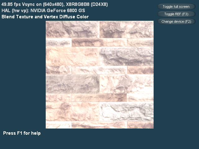
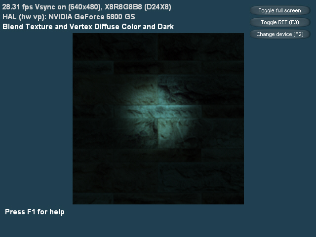
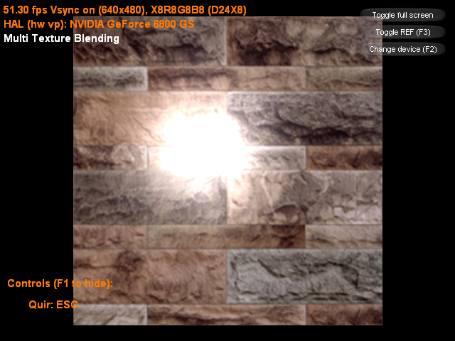
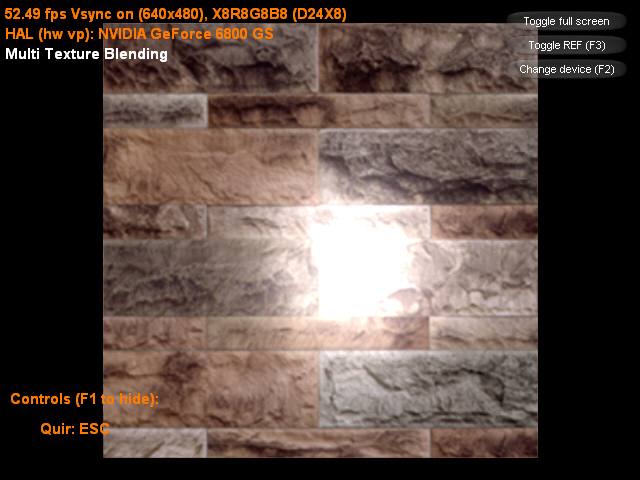
这里先将物体的漫反射颜色和纹理层0的纹理颜色相乘,得到的结果再与纹理层1的纹理颜色相加后输出。
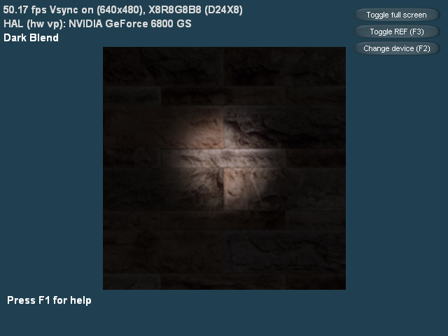
该示例将物体纹理和光照纹理相混合后输出:
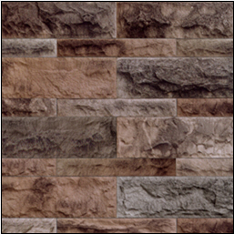
物体纹理
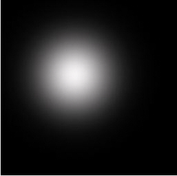
光照纹理
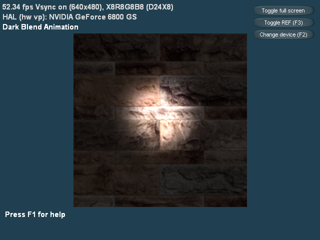
运行效果图如下:
我们可以修改顶点的纹理坐标为:
sCustomVertex vertices[] = { { -3.0f, -3.0f, 0.0f, 0xffffffff, 0.0f, 1.0f, 1.0f, 0.0f}, { -3.0f, 3.0f, 0.0f, 0xffffffff, 0.0f, 0.0f, 1.0f, 1.0f}, { 3.0f, -3.0f, 0.0f, 0xffffffff, 1.0f, 1.0f, 0.0f, 0.0f}, { 3.0f, 3.0f, 0.0f, 0xffffffff, 1.0f, 0.0f, 0.0f, 1.0f}};
这时的运行效果图如下:
|


 IP卡
IP卡 狗仔卡
狗仔卡 发表于 2009-3-4 09:16:09
 提升卡
提升卡 置顶卡
置顶卡 沉默卡
沉默卡 喧嚣卡
喧嚣卡 变色卡
变色卡 千斤顶
千斤顶 显身卡
显身卡 楼主
楼主 erform any application-level initialization here